Loading...
Loading...

Hardware

Introduction

This project aims to provide breakthrough treatment solutions for eye diseases such as cataracts, with a focus on a long-acting drug delivery platform based on hydrogel contact lenses. The platform utilizes bioengineered miniature bioreactors to continuously secrete therapeutic components, such as RNF114. By adhering to the surface of the eye, the contact lenses overcome the issues of low drug absorption rates and short retention times associated with traditional eye drops, fundamentally improving the effectiveness of drug treatment while reducing systemic toxicity and the burden of frequent administration.

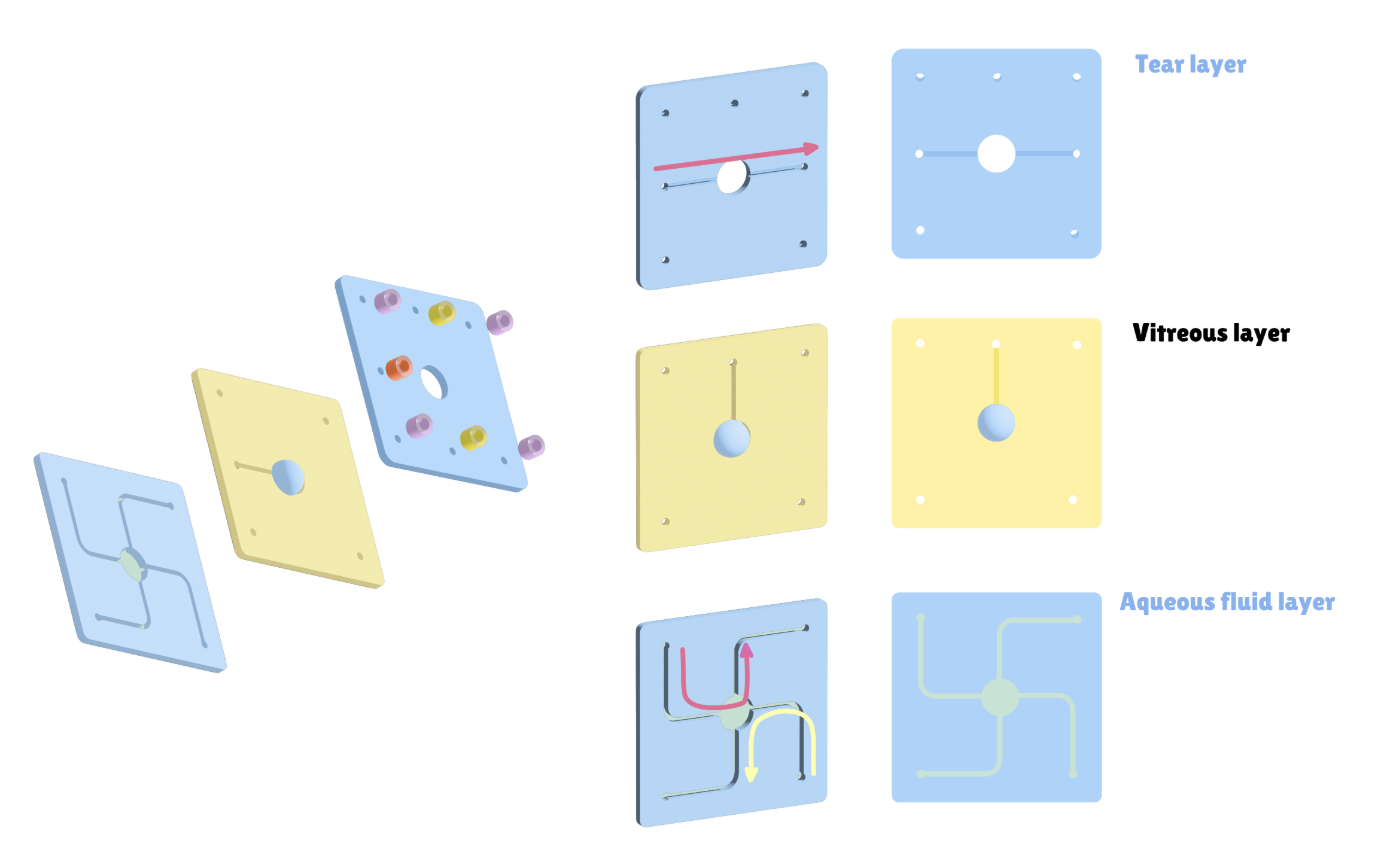
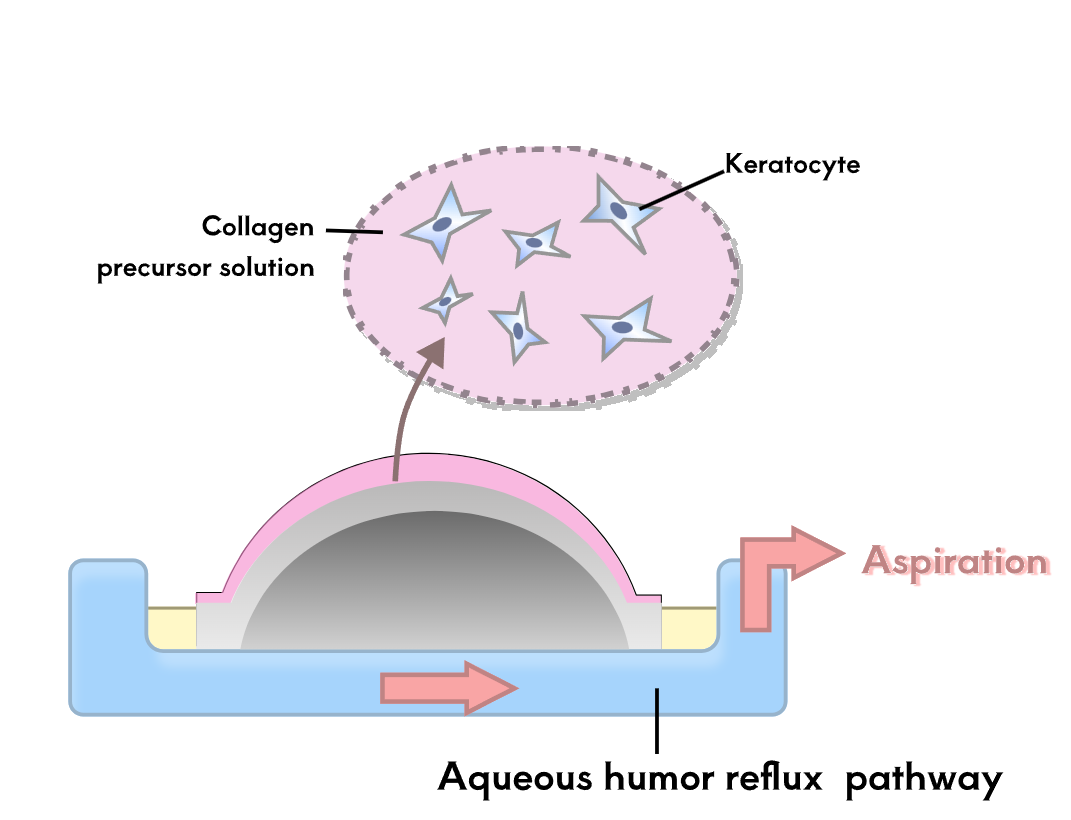
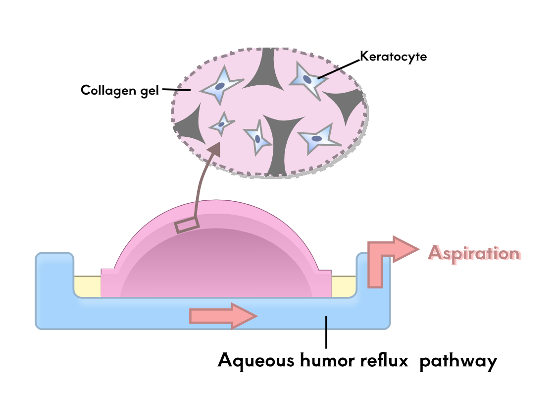
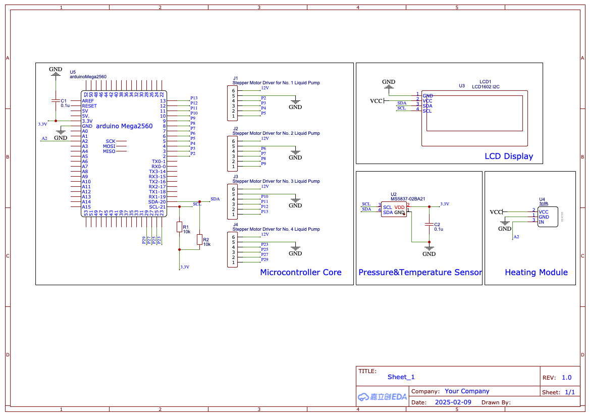
To test the therapeutic effect of the developed contact lenses, it is necessary to conduct biological experiments to verify the sustained release of RNF114 and the final amount of drug delivered to the lens. Since animal experiments are not within the scope of iGEM, we utilize microfluidic technology by stacking multilayer chips to simulate the drug delivery path in the human eye. This approach enables convenient, fast, and reproducible experiments, while also providing an iterative solution for the evaluation of ocular drug delivery.

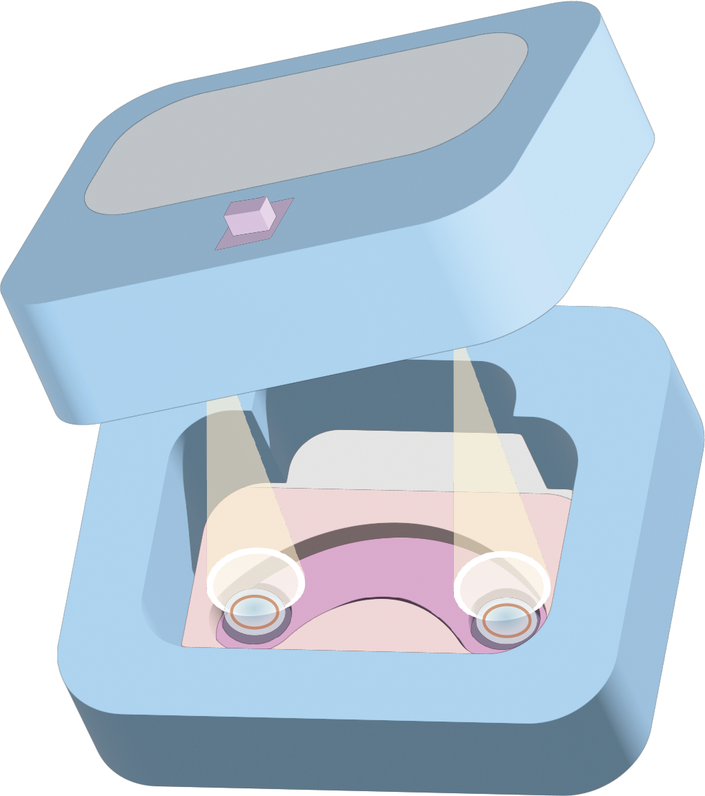
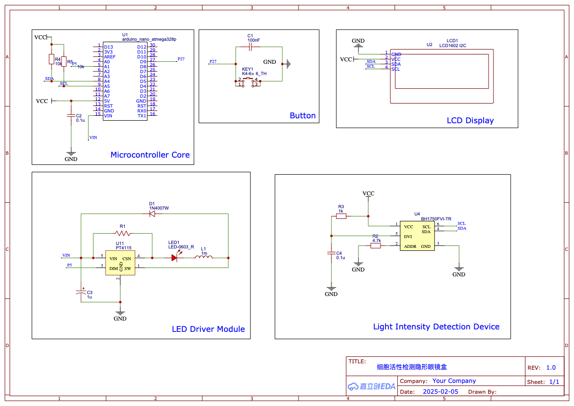
At the same time, to alert users to replace the contact lenses in time when the microbial activity declines, ensuring that the microbes remain highly active and continue to effectively secrete RNF114 while avoiding contamination of the eye from the microbial lysate, we have designed a user-friendly contact lens case. This case integrates a fluorescence detection device, which detects the active fluorescent signal emitted by the embedded bioreactors in the contact lenses. This helps users quickly determine whether the contact lenses are still active and safe for continued use.

Here are the two devices we designed:
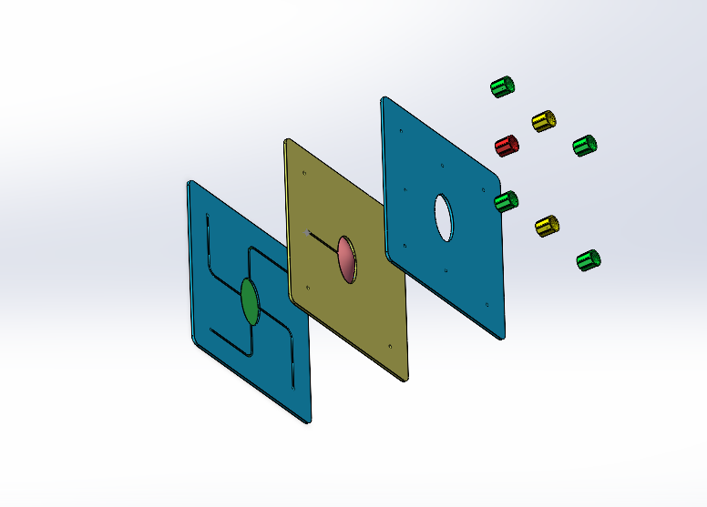
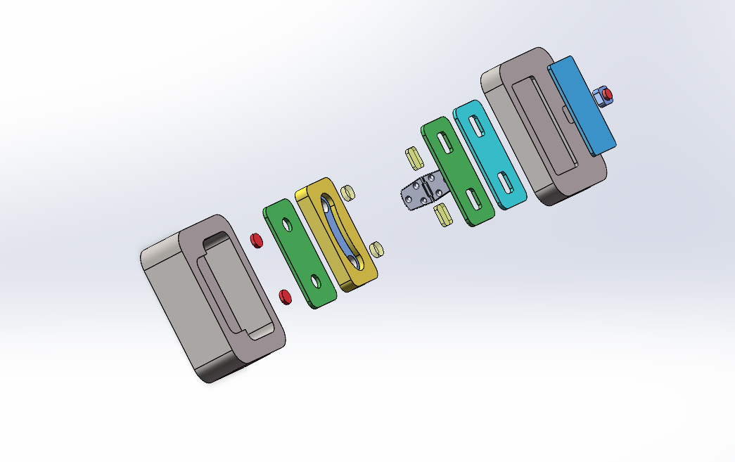
  1. Eye Simulation Chip
  2. Cell Activity Detection Contact Lens Case

Eye Simulation Chip

Appearance

To detect the drug content that reaches the lens, we will simulate the drug delivery method using contact lenses on the eye. At predetermined time points, we will pause the aqueous humor reflux, collect the instantaneous aqueous humor, and then reinject the aqueous humor to continue circulation, in order to measure the drug concentration within it. The specific process can be found in Wet Lab-Engineering-Production Expression Verification Module-Cycle3.

We need to simulate the process of the drug moving from the contact lens, through the tear film layer, across the cornea, and finally reaching the aqueous humor reflux.

The eye simulation chip we designed consists of three parts, as shown in the diagram from top to bottom (the main material of the chip is PDMS,and the pipeline interfaces above the tear film layer chip is connected to the liquid pumps.):

Eye Simulation Chip Layers

Tear layer

We use periodic pulses to drive the peristaltic pump, simulating the flow of the tear film and the flushing effect caused by intermittent blinking.

Eye Simulation Chip Tear Layer

Cornea layer

We proceeded with the corneal layer construction as follows:

Eye Simulation Chip Cornea Layer
  1. Production of cell culture scaffolds: We use compression molded polystyrene cell culture media (Alvetex®, Reprocell). The 3D printed molds were used to compress and heated at 100°C for 15 min to induce permanent deformation, resulting in a corneal layer medium that conformed to the radius of curvature, which was set at 7 mm.
  2. Eye Simulation Chip Cornea Layer
    Eye Simulation Chip Cornea Layer
  3. Corneal stromal
    1. Corneal stromal formation: Primary human keratocytes were trypsinized and suspended in a solution prepared by mixing rat tail type 1 collagen (2 mg/ml) with deionized water, 10X PBS, and 1N NaOH. The final concentration of suspended cells was 1 million cells/ml. In the next step, 25 µl of this cell-containing collagen precursor solution was dispended on the scaffold surface and then gently suctioned through a channel in the aqueous layer into the hole in the stent. Gelation of collagen was achieved by incubating the seeded device in a humidified cell culture incubator (37 ºC, 5% CO2) for 30 minutes.
    2. Eye Simulation Chip Cornea Layer Eye Simulation Chip Cornea Layer
      Eye Simulation Chip Cornea Layer
    3. Corneal cell inoculation: controlled cell suspension adherence to a gelatinized stromal surface
    4. Eye Simulation Chip Cornea Layer
      Eye Simulation Chip Cornea Layer
  4. Corneal layer assembly
    1. Corneal layer plate material: PDMS
    2. The shaped medium was bonded to the PDMS plate by polymerization reaction, and the substrate construction and cell inoculation were carried out sequentially
    3. A layer of PDMS was attached to the bottom layer to simulate the iris.

The design considerations include:

  • Symmetrical fluid flow paths to ensure uniform distribution
  • Precise pressure control through PID feedback system
  • Temperature regulation to maintain physiological conditions
  • Biomimetic outflow resistance using PDMS membrane

Aqueous humor drainage layer

Based on the aqueous humor reflux pathway, we designed a symmetric liquid flow direction and pump drive system. Specifically, we placed an MS5837 sensor below the waterproof layer to detect the hydraulic pressure and temperature of the aqueous humor. Through PID control, we adjust the flow rate difference of the aqueous humor being pumped in and out to stabilize the internal hydraulic pressure. Additionally, a small heating module is integrated to control the temperature of the aqueous humor. At the outlet, a simple PDMS membrane is used to simulate the trabecular meshwork and Schlemm's canal.

Here are the SolidWorks 3D modeling exploded view, part drawings, and assembly files, showcasing the specific structure and assembly method of each layer of the chip.

Assembly view
Assembly View

Circuit Design

Eye Simulation Chip Process Flowchart

The circuit design consists of four main components:

  1. Microcontroller Unit (MCU)
  2. The control core of the system. The eye simulation chip will use an Arduino Mega as the main control chip. It has a large number of pins, which makes it easier to expand the system in the future. Additionally, it has strong data processing capabilities, enabling more precise control and simulation of the eye's physicochemical properties.

  3. MS5837 Sensor
  4. An integrated temperature and pressure sensor, with a pressure accuracy of 0.2 kPa. It meets the requirements for controlling intraocular pressure and can also measure temperature, providing feedback to simulate the eye's temperature.

  5. Stepper Motor Peristaltic Pump
  6. By controlling the rotational speed of the stepper motor, the flow rate of the peristaltic pump can be adjusted to simulate the tear fluid flushing and aqueous humor reflux. Additionally, by controlling the inflow and outflow of the aqueous humor, the system can regulate intraocular pressure.

  7. Heating Module
  8. The heating module is controlled based on feedback from the temperature sensor, adjusting the heating speed to stabilize the temperature within the aqueous humor, simulating the eye's natural thermal conditions.

The complete circuit schematics and PCB design files are available in the supplementary materials.

Eye Simulation Chip Circuit Diagram

Main Function Code

The control system implements PID control for pressure regulation and temperature monitoring. Here's the main function code:

eye_simulation_control.cpp

#include  
#include 
#include 
#include   // I2C LCD library

// Basic pump speed
const double baseSpeed = 2000;

// PID parameters
double Kp_Pressure = 2.0;  
double Ki_Pressure = 1.0;  
double Kd_Pressure = 0.5;  

double Kp_Temperature = 20.0;  

// Target pressure 10-21mmHg,target temperature 35°C
double targetPressure = 1500.0;  // Target pressure set to 1500 Pa
double targetTemperature = 35;  // Target temperature set to 35°C

// Current values
double currentPressure = 0.0;    // Current pressure (Pa)
double currentTemperature = 0.0;  // Current temperature

// PID variables
double error_Pressure, previousError_Pressure = 0.0;
double I_Pressure = 0.0;
double D_Pressure = 0.0;
double output = 0.0;

// Stepper motor setup (AccelStepper configuration)
AccelStepper pumpIn(AccelStepper::DRIVER, 3, 4);    // First pump group (In)
AccelStepper pumpOut(AccelStepper::DRIVER, 7, 8); // Second pump group (Out)
AccelStepper pumpIn_tear(AccelStepper::DRIVER, 11, 12);    // First tear pump group (In)
AccelStepper pumpOut_tear(AccelStepper::DRIVER, 25, 27); // Second tear pump group (Out)

// Initialize MS5837 sensor
MS5837 sensor;

// Initialize I2C LCD screen (address: 0x27, 16 cols 2 rows)
LiquidCrystal_I2C lcd(0x27, 16, 2);

// Variables for time-based pulse speed increase
unsigned long lastPulseTime = 0;  // Last time a pulse was added
const unsigned long pulseInterval = 5000;  // 5 seconds interval for increasing speed
const unsigned long pulseDuration = 1000;  // Duration to hold increased speed (1 second)
int pulseIncrement = 100;  // Amount to increase speed by each pulse
double tearSpeedIncrement = 0;  // Tear pump speed increment

unsigned long pulseEndTime = 0;  // Time when the high-speed duration ends

const int pwmPin = 2;

void setup() {
    // Initialize stepper motors
    pumpIn.setMaxSpeed(1000);  
    pumpIn.setAcceleration(500);  
    
    pumpOut.setMaxSpeed(1000);  
    pumpOut.setAcceleration(500);  
    
    pumpIn_tear.setMaxSpeed(1000);  
    pumpIn_tear.setAcceleration(500);  
    
    pumpOut_tear.setMaxSpeed(1000);  
    pumpOut_tear.setAcceleration(500);  
    
    // Initialize sensor
    Wire.begin();

    // Initialize LCD screen
    lcd.begin();
    lcd.backlight(); 
    lcd.setCursor(0, 0);
    delay(2000); 

    // heating module
    pinMode(A2, OUTPUT);
}

void loop() {
    // Read sensor data
    sensor.read();
    currentPressure = sensor.getPressure() * 100.0;  // Convert mbar to Pa
    currentTemperature = sensor.getTemperature(CELSIUS);

    // Calculate error
    error_Pressure = targetPressure - currentPressure;
    
    // Calculate I and D terms
    I_Pressure += error_Pressure;
    D_Pressure = error_Pressure - previousError_Pressure;
    
    // Calculate output
    output = Kp_Pressure * error_Pressure + 
            Ki_Pressure * I_Pressure + 
            Kd_Pressure * D_Pressure;
    
    // Control pumps based on output
    controlPumps(output);
    
    // Sync tear pumps and increase speed every 5 seconds
    syncTearPumpsAndIncreaseSpeed();

    // Save current error for next derivative calculation
    previousError_Pressure = error_Pressure;

    // Display pressure and temperature on LCD
    displayDataOnLCD(currentPressure, currentTemperature);

    delay(100);
}

// Pump control function
void controlPumps(double output) {
    // Adjust pump speeds based on PID output
    double pumpInSpeed = constrain(output + baseSpeed, 0, 1000); 
    double pumpOutSpeed = constrain(-output + baseSpeed, -1000, 0);
    
    // Set stepper motor speeds
    pumpIn.setSpeed(pumpInSpeed);  
    pumpOut.setSpeed(abs(pumpOutSpeed));
    
    // Run motors
    for(int i = 0; i < 10; i++) {
        pumpIn.runSpeed();
        pumpOut.runSpeed();
        pumpIn_tear.runSpeed();
        pumpOut_tear.runSpeed();
    }
}

// Function to sync tear pumps and increase speed every 5 seconds
void syncTearPumpsAndIncreaseSpeed() {
    unsigned long currentMillis = millis();
    
    // Check if it's time to increase speed
    if (currentMillis - lastPulseTime >= pulseInterval) {
        // Increase speed for tear pumps
        tearSpeedIncrement += pulseIncrement;
        
        // Set the new speed for both tear pumps
        pumpIn_tear.setSpeed(tearSpeedIncrement);
        pumpOut_tear.setSpeed(tearSpeedIncrement);
        
        // Update the last pulse time and set the pulse end time
        lastPulseTime = currentMillis;
        pulseEndTime = currentMillis + pulseDuration;  // Set the end time for the high-speed phase
    }

    // Check if it's time to restore the speed to base speed
    if (currentMillis >= pulseEndTime) {
        // Restore speed to original value
        pumpIn_tear.setSpeed(tearSpeedIncrement - pulseIncrement);
        pumpOut_tear.setSpeed(tearSpeedIncrement - pulseIncrement);
    }
    //heating
    if(temperature < targetTemperature){
        analogWrite(pwmPin, Kp_Temperature*(targetTemperature-temperature));
    }else{
        analogWrite(pwmPin, 0));
    }
}

// Display pressure and temperature data on LCD screen
void displayDataOnLCD(double pressure, double temperature) {
    lcd.clear();
    
    // Display pressure
    lcd.setCursor(0, 0);
    lcd.print("P: ");
    lcd.print(pressure);
    lcd.print(" Pa");
    
    // Display temperature
    lcd.setCursor(0, 1);
    lcd.print("T: ");
    lcd.print(temperature);
    lcd.print(" C");
}

Cell Activity Detection Contact Lens Case

Appearance

To facilitate daily detection of cell activity in the contact lenses, we have designed a user-friendly cell activity detection device that integrates a laser emission system and light intensity detection system while storing the contact lenses. The fluorescent protein Crimson has an excitation/emission peak wavelength of 588/617 nm[4]. After exciting the fluorescent protein with a laser, the BH1750 sensor is used to detect the emitted light intensity from the engineered bacterial cells.

In the wet lab portion, under simulated eye conditions, we track and monitor the engineered bacterial cell density and corresponding fluorescence signal intensity. By analyzing the fluorescence signal data of the engineered bacteria from the growth phase, plateau phase, to apoptosis phase, we identified three safety levels—"Safe", "Replace Recommended", and "Not Usable"—each corresponding to a specific fluorescence signal intensity. We then compare the light intensity values detected by the BH1750 sensor with the experimental threshold values for each safety level. The real-time safety level of the cells is displayed on an LCD screen, allowing users to easily determine whether the contact lenses can still be used safely.

Components

The eye simulation chip we designed consists of several parts, as shown in the diagram:

Cell Activity Detection Contact Lens Case
  1. Contact Lens Case Shell
  2. Laser Emission Device
    1. 590-595 nm LED
    2. LED driver chip
    3. 590 nm filter
  3. Light Intensity Detection Device
    1. 620 nm filter
    2. BH1750 light intensity sensor
  4. LCD Display

CAD Models

Here are the SolidWorks 3D modeling exploded view, part drawings, and assembly files, showcasing the specific structure and assembly method of the contact lens case.

Circuit Design

Exploded view of the contact lens case
Cell Activity Detection System Process Flowchart
  1. Microcontroller Unit (MCU)

    We selected the Arduino Nano, as the main control chip is small and convenient for placement inside the contact lens case.

  2. Laser Emission Device

    Driven by the PT4115 LED driver, it uses constant current control to ensure the LED brightness remains stable and unaffected by power supply voltage fluctuations, ensuring the stability of cell activity detection. Based on data from the reference [4], we chose a 565 nm/30 nm LED, with a 568/20 nm excitation filter.

  3. Light Intensity Detection Device

    The fluorescence emitted by the cells passes through a 620/60 nm emission filter and is detected by the BH1750. The BH1750 offers a high detection accuracy of up to 0.5 lx, enabling precise measurement of fluorescence intensity to determine cell activity.

  4. Button & Display

    The button, when pressed, activates the light intensity detection system, and the results are displayed on the LCD screen, providing a user-friendly detection system.

Circuit diagram of the contact lens case
Circuit diagram of the cell activity detection system

Main Function Code

The main function code is as follows:

cell_activity_detection.cpp

#include 
#include 
#include 

const int bottom = 27;     // Button pin
const int pwmPin = 5;      // PWM output to PT4115 DIM pin

//threshold
const double Safe_threshold = 200;
const double Replace_Recommended_threshold = 100;
const double Not_Usable_threshold = 50;

LiquidCrystal_I2C lcd(0x27, 16, 2);  // I2C address 0x27, 16x2 LCD
BH1750 lightMeter;

int brightness = 128;      // Initial brightness (0-255)
bool ledOn = false;        // LED switch state
const int threshold = 200; // Light intensity threshold (lux)

void setup() {
    pinMode(encoderSW, INPUT_PULLUP); // Use internal pull-up resistor
    pinMode(pwmPin, OUTPUT);
    analogWrite(pwmPin, brightness);  // Initialize brightness
    
    // Initialize LCD and BH1750
    Wire.begin();
    lcd.begin();
    lcd.backlight();
    lightMeter.begin();
    lcd.setCursor(0, 0);
    lcd.print("Initialized successfully!");
    delay(1000);
    lcd.clear();
}

void loop() {
    handleButton();     // Button controls LED and light intensity detection
}

void handleButton() {
    if (digitalRead(bottom) == LOW) { // Detect button press
        delay(50); // Debounce
        lcd.clear();

        ledOn = true;
        analogWrite(pwmPin, brightness);
        lcd.setCursor(0, 0);
        lcd.print("LED ON: 5 sec");
        delay(5000);

        float lux = lightMeter.readLightLevel(); 
        lcd.setCursor(0, 1);
        lcd.print("Light: ");
        lcd.print(lux);
        lcd.print(" lux");

        lcd.setCursor(12, 1);
        if (lux >= Safe_threshold) {
            lcd.print("Safe");  
        } else if (lux >= Replace_Recommended_threshold){
            lcd.print("Replace_Recommended"); 
        } else {
            lcd.print("Not_Usable"); 
        }
        
        analogWrite(ledPin, 0);
        
        delay(2000); 
        lcd.clear();
    }
}

Reference

[1] Bennet D, Estlack Z, Reid T, et al. A microengineered human corneal epithelium-on-a-chip for eye drops mass transport evaluation. Lab on a Chip, 2018, 18(11): 1539-1551. DOI: 10.1039/C8LC00158H
[2] Seo J, Byun W Y, Alisafaei F, et al. Multiscale reverse engineering of the human ocular surface. Nature Medicine, 2019, 25(8): 1310-1318. DOI: 10.1038/s41591-019-0531-2
[3] Estlack Z, Bennet D, Reid T, et al. Microengineered biomimetic ocular models for ophthalmological drug development. Lab on a Chip, 2017, 17(9): 1539-1551. DOI: 10.1039/C7LC00112F
[4] Ning L, Yang G, Lovett-Barron M, et al. A bright, nontoxic, and non-aggregating red fluorescent protein for long-term labeling of fine structures in neurons. Frontiers in Cell and Developmental Biology, 2022, 10: 893468. DOI: 10.3389/fcell.2022.893468